Installing N4DK's SteppIR 3el 6-40M Antenna
Roswell, Georgia
..This page is best viewed full-screen at 1024x768 resolution or above..
While impressed with the design and reports of good performance, friend Don Kasten N4DK waited until SteppIR announced the 30-40 meter element availability on their popular 3el antenna. The idea of having an (effectively) infinite number of monoband antennas covering 6 through 40 meters was very appealing; Don placed his order for a new 3el SteppIR with the 30-40M element on April 4, 2006.
Demand for this new feature was massive. SteppIR decided to ship 30-40M "add-on" kits to their existing 3el and 4el SteppIR owners first. This forced a delay in new antennas with this feature -- but it was worth the wait.
When they began shipping new antennas, Don received the third-to-be-shipped all-new 6-40M 3el SteppIR in mid-November 2006 and set about planning the installation.
He called several ham buddies in to help. Chief among these was Jim Streible K4DLI who, besides owning a 4el SteppIR himself, had participated in construction and installation of a SteppIR MonstIR antenna at the QTH of Bob Carroll, W2WG. Bob was added to the team as well as Don Nesbitt N4HH, Jerry Frost WD4AHF and me, Chaz Cone W4GKF. Altogether we had three existing SteppIR owners (that ought to be enough!) though none of us had ever had our hands on the new 30-40M driven element (the "trombone").
 |
 |
 |
| Don, N4DK | Jim, K4DLI | Bob, W2WG |
 |
 |
 |
| Don, N4HH | Jerry, WD4AHF | Chaz, W4GKF |
Food, drink and spousal support was provided by Don's XYL, Karen N4UBZ:

Wednesday, November 15
The antenna arrived in two boxes:
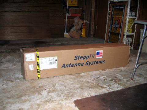
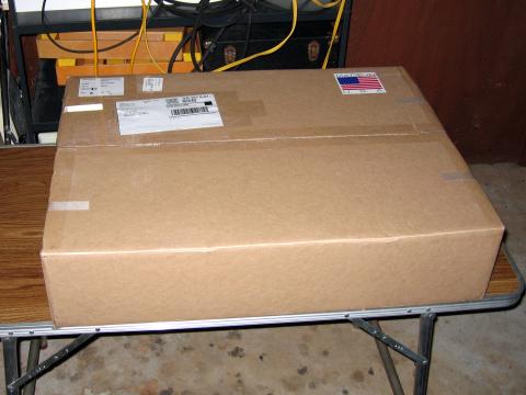
This shows the contents of the smaller box. The black semicircular pieces are the end-pieces for the driven element; with four EST (Element Support Tubes), they form the "trombone"-shaped driven element used as a dipole on 30 and 40 meters and as the driven element of the 3el beam for 6-20meter operation:

You can see it a bit better in this shot as Jim K4DLI holds one up:

For those not familiar with the SteppIR components, they consist of:
- A 16' boom (shipped in four pieces)
- A set of fiberglass Element Support Tubes (ESTs) each made of three nesting tubes. For the 3El antenna with the 30-40M feature, there were eight such tubes.
- A set of Element Housing Units (EHUs) containing the stepper motor and the copper-beryllium tape that forms the radiating elements. For the 3El antenna there are three EHUs. Two identical ones (for the Director and Reflector) and one with a SO-239 coax connector for the Driven Element.
- A control box that provides instructions to the EHUs in oparation.
- Various connectors and a multi-conductor cable connecting the EHUs with the Control box. For the 3El antenna the cable is 12-conductor.
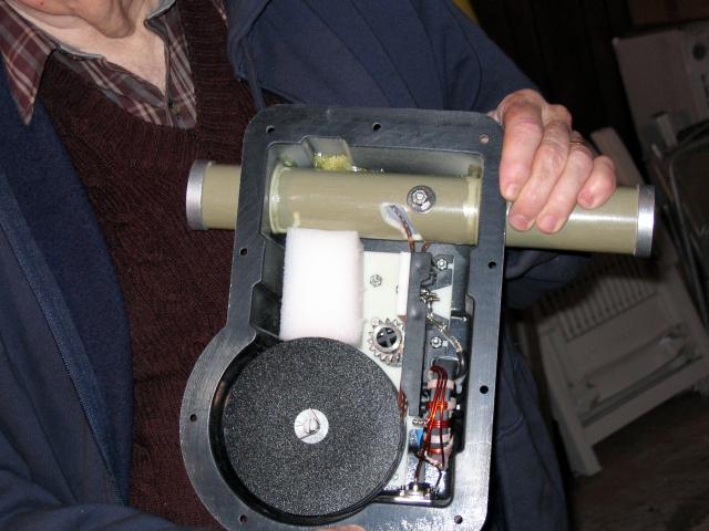
Don and Jim unpacked everything to make sure all was in order. The Driven Element EHU was shipped with the cover off and instructions to remove a foam shipping block meant to protect the drive sprockets in shipment. For some reason, no such shipping block was used in the Director and Reflector EHUs. At any rate it was interesting to see the works inside the EHU:
Don had ordered his boom powder-coated black (an ordering option). He felt that this would make the antenna less obtrusive than the standard aluminum tube look. The EHU mounting plates and the boom-to-mast bracket (all powder-coated) were already mounted and aligned; it was a simple matter to slide and bolt the four boom sections together:
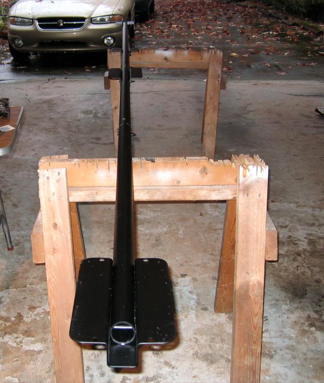

NOTE: Here you can see that we switched the U-bolts for the boom to mast plate;
read on for more about that error!
Saturday, November 18
Weather had been poor on Thursday so all that had been accomplished was to complete the parts inventory, make a hardware store run for some extra stainless steel screws and to lay out the work for today. One of the most time-consuming parts of the project was the preparation of the ESTs:

Each EST displays a Steppir Logo
There are eight ESTs; four are used for the Director and Reflector elements and have foam plugs in the small end. The other four are used for the Driven element; they are open on the small end and have a band of high-friction, sandpaper-like tape near the small end. The construction steps are:
- Pull the telescoping sections of each EST out and twist until they lock in position. Each EST is about 18' long
- Wrap each joint (there are three on each EST) with electrical tape.
- Wrap each joint with silicon tape; a special tape that adheres only to itself.
- Wrap each joint with another coating of electrical tape.
Though the instructions didn't call for it, Jim also used "liquid electrical tape" (available at Home Depot) to coat the ends of the final tape wrap to encourage them to stay down.
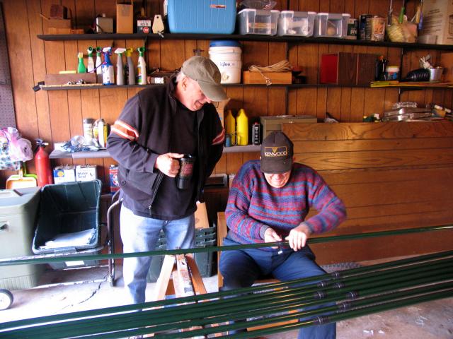
This is one of a series of photos showing Don N4HH looking on while Jim K4DLI does all the work..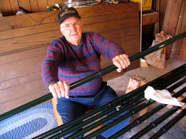
Once the ESTs were finished, we moved the boom out to the driveway to attach the EHUs:

To assist in keeping the boom from rolling along the sawhorses, Jerry devised a "roll prevention anchoring device" from a piece of dowel:
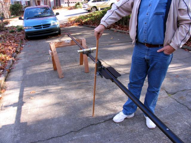
Our leader Jim, having done this more than once, checked the position on the boom and marked the Director and Reflector EHUs so we wouldn't get confused when wiring (and orienting the antenna later):
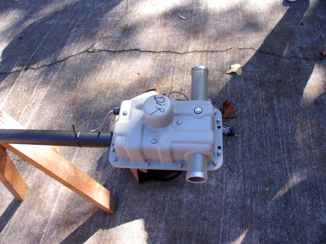
We found it necessary to temporarily loosen the factory-installed bolts clamping the EHU mounting brackets to the boom in order to get the mounting screws aligned properly:
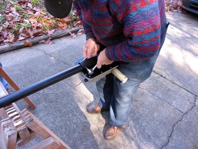
We trial-fit each of the ESTs into an EHU to make sure the fit was snug. Two of the ESTs required a little bit of sanding to make them slide easily:

Once we were satisfied that the ESTs would mate properly, we removed them and turned our attention to wiring the EHUs. This is a task that ABSOLUTELY requires paying attention to the wiring diagram in the manual:
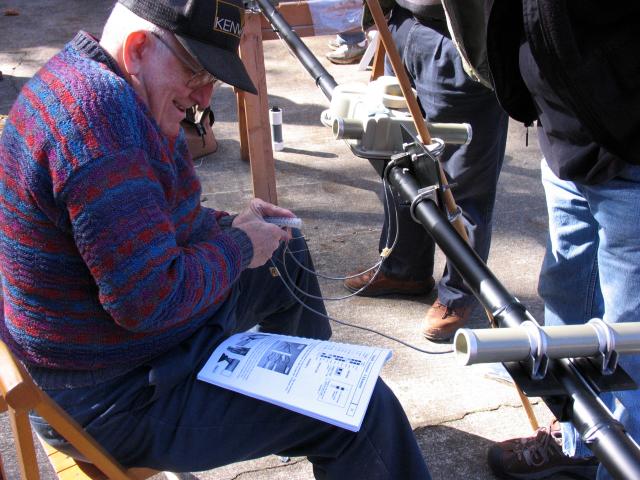
All twelve conductors were uniquely colored, making it a no-brainer to get the wiring right:
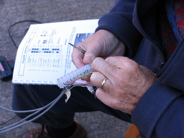
Jim trimmed about half the tinned lead from each wire to ensure each would fit handily into the terminal block. He also shortened the lead from the Driven Element EHU by about a foot. SteppIR supplies a packet of corrosion-resistant gel that's used to dip each tinned lead before attachment to the terminal block.
Once the wiring was done and checked, we hooked up the controller to test the wiring:
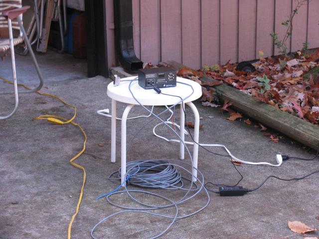
While we expected that the controller had been shipped with the programming set to "Elements Retracted", before connecting the cable to the antenna we turned the controller on just to be sure. The controller was set to "Elements Retracted" so we turned it off. We connected the cable, turned on the controller, and used the "Test" mode to see if the EHUs would behave as expected.
In Test Mode, you choose each EHU in turn and it spits out just enough tape to make the "bullet" on the end of the tape visible at the EST attachment guide:
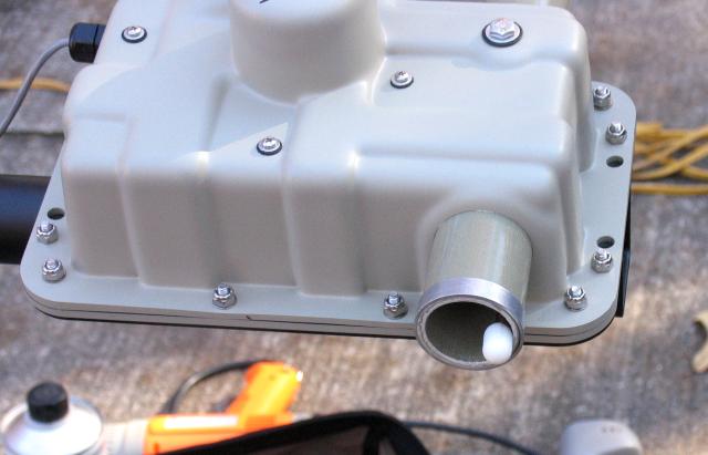
Each EHU worked perfectly! We "homed the elements, turned off the controller and disconnected the cable.
Next we used black UV-resistant cable ties to dress the cables from each EHU to the boom. Jim covered each of the cable ties with electrical tape and used "liquid tape" to secure the end of each wrap. He also used "liquid tape" on the connectors where each control cable emerges from the EHU:
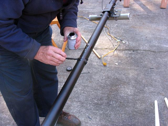
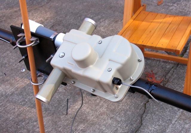
Though the instructions didn't say to do so, Jim wrapped the terminal strip with electrical tape before inserting it into the capped PVC tube supplied for that purpose. He loosely attached the tube to the mast plate; it will be secured later when the mast is attached to the boom:
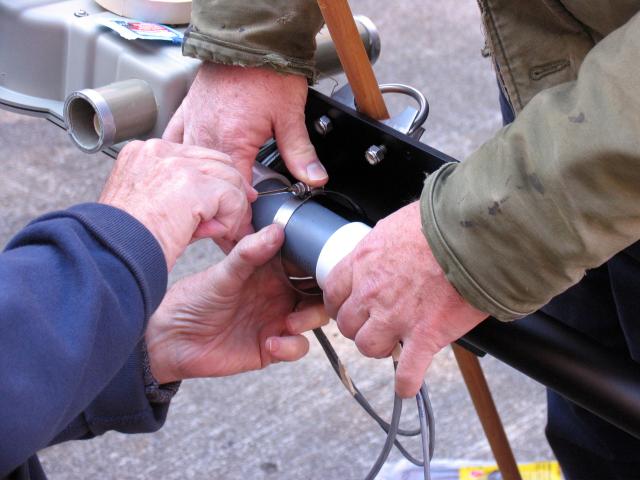
Then the cables were dressed together and taped and the end secured with "liquid tape":

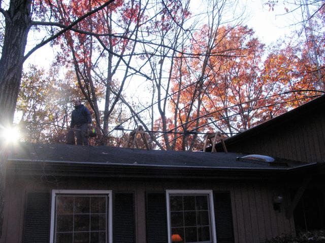
With the boom assembly complete and tested, we decided to move the boom and all the ESTs up onto the garage roof. Don's home is a split level and the lower roof has a gentle pitch; because of trees we elected to complete the assembly of the antenna on the roof.
Fallen leaves had left the roof a little slippery and, since none of us were "spring chickens" Don N4HH got up there first and blew all the leaves off:

After we got all the parts on the roof:
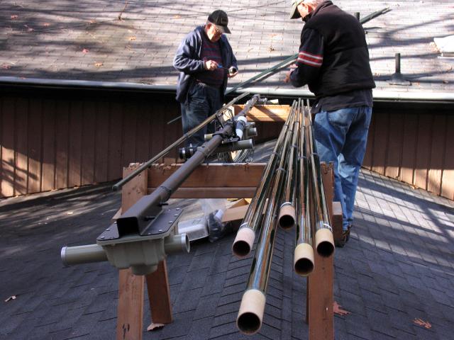
..someone suggested that the manual might be helpful so Karen handed it up:
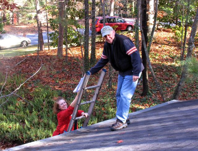
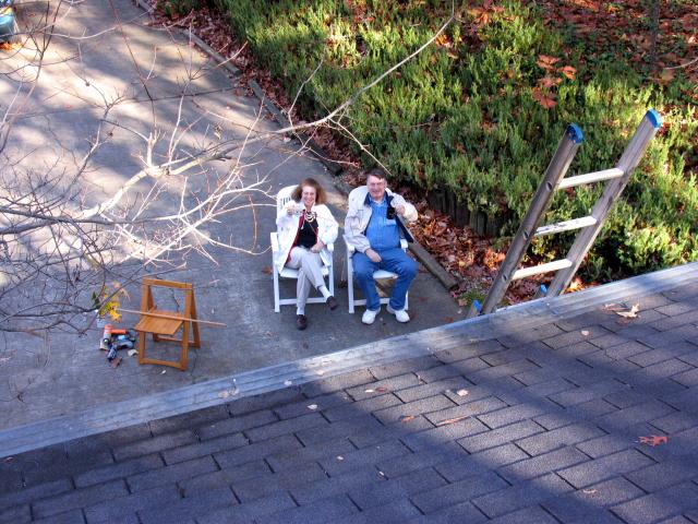
We left Karen and Jerry on the ground to call for ambulances if necessary while the rest of us old men were on the roof:
Installing the Director and Reflector ESTs were easy as pie. Slide on the rubber boot, tape them liberally with electrical tape, slide in the ESTs and clamp 'em down:
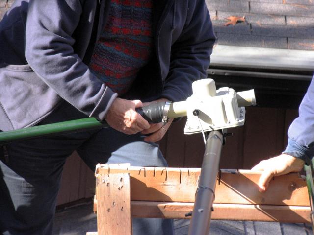
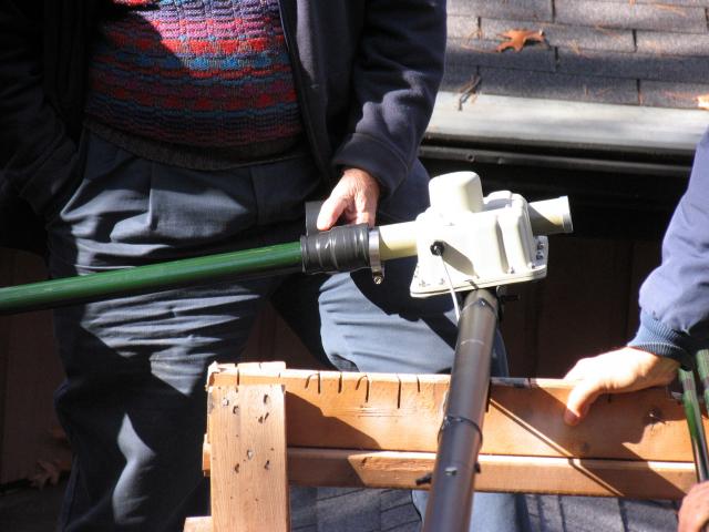
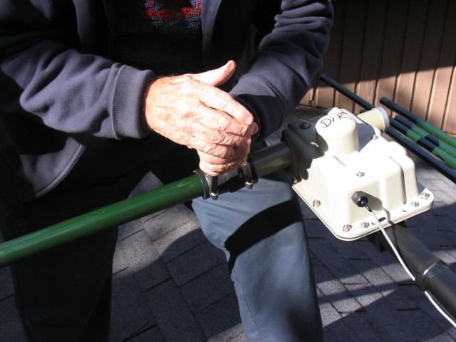
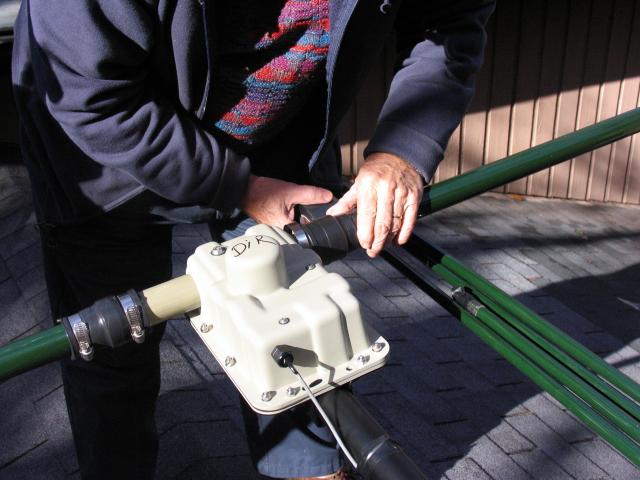
Since the clamps are compressing rubber, we'll have to re-tighten several times before sending the antenna up the tower.
The Driven Element was more of a challenge. On this antenna, the Driven Element uses two ESTs and a semicircular tube with a horizontal brace to connect to the Driven Element EHU:
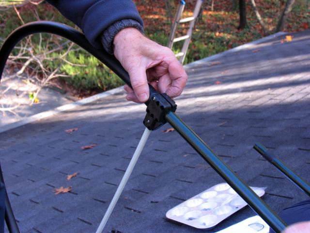
Putting these assemblies together (one for each side of the boom) was a bit challenging while on a pitched roof -- but Jim was equal to the job. The semicircular tube attaches with a set of small screws and lock nuts:

You have to use a screwdriver to wedge the opening a bit wider to slide in the tip of the EST; like this:
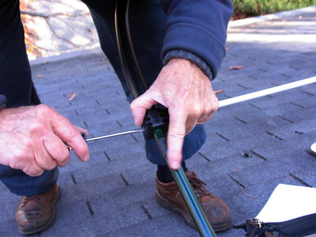
That "sandpaper" band behind Jim's left index finger has to slide into the clamp..
After the Driven Element ESTs and semi-circular tube assemblies are done, Jim installed the white extension tubes into the openings on the Driven Element EHUs. The PVC liquid adhesive is supplied and the tube mates neatly with a tube inside the EHU. The adhesive dries in ten seconds leaving a white tube extending from the Driven Element EHU about three feet:
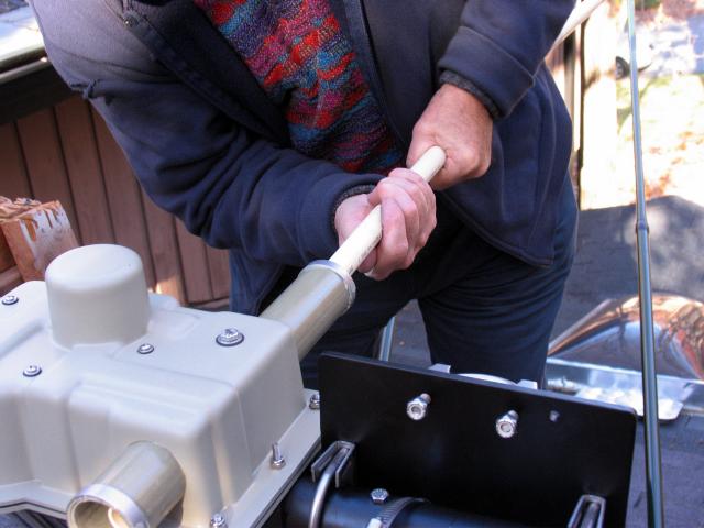
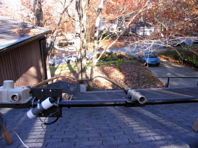
On 30 and 40 Meters, the tape extends from the Driven Element EHU out 18', through the semicircular tube and back down toward the boom (like a folded dipole). In this mode, the Director and Reflector Elements are fully retracted.
Once the ESTs were attached it was time for the "smoke test". Well, we used an Antenna Analyzer so there was no chance of real smoke! With the Director lying on the upper roof and the rest of the antenna supported by sawhorses, we didn't expect 1:1 SWR on the resonant frequency -- and, sure enough, we didn't get it! The antenna resonated about 300-500KHz lower in frequency on all bands than the controller indicated; we're sure it will be excellent when in place on the tower. Here's Jim with the final test of the day:
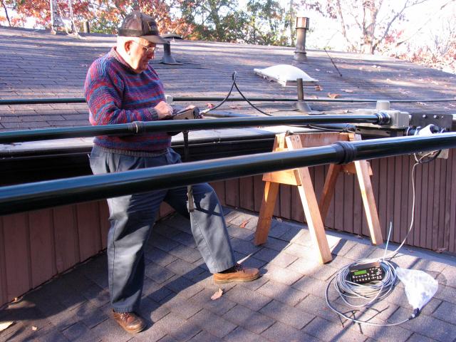
Here's the completed antenna on the lower roof ready for installation on the tower (tomorrow):
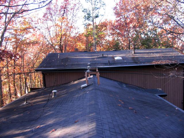
Here's today's crew; we all survived!
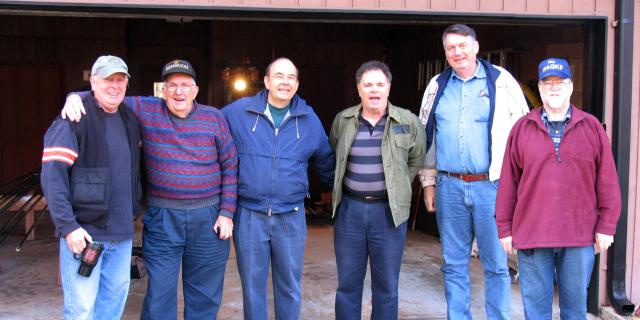
Don N4HH, Jim K4DLI, Bob W2WG, Don N4DK, Jerry WD4AHF, Chaz W4GKF
Sunday, November 19
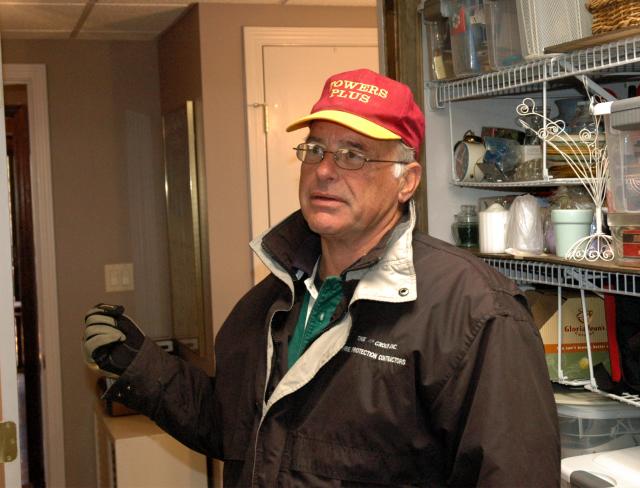
The project restarted at 9am today with the arrival of Louie Lincoln WP2A of "Towers Plus" and his helper, Mike:
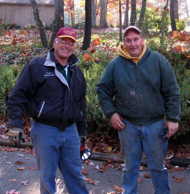
If you have tower work in the Atlanta area, you can contact Louie by clicking
.
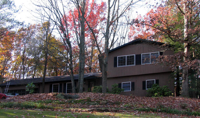
The house was pretty much as we left it; you can barely see the antenna on the lower roof and the 30' Rohn 25 tower mounted on the upper roof:
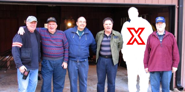
Don N4HH, Jim K4DLI, Bob W2WG, Don N4DK, Chaz W4GKF
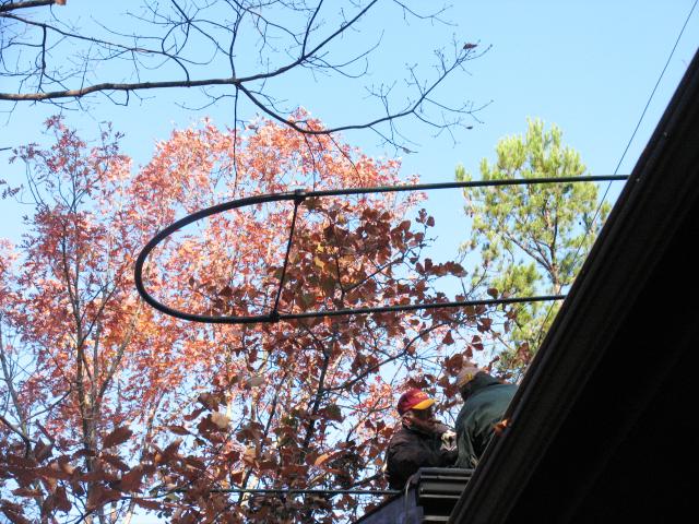
Here's Louie and Mike seen with the "trombone" SteppIR Driven Element:
The work project today was to:
- Remove the two ancient sets of steel guy wires and replace them with one new set using Phillystran
- Raise the SteppIR and mount it to the tower on a 10' mast
- Check it all out and finish the project
Louie spent a couple of hours on the guys; seems that one set was attached to the roof using lagscrew eyebolts (the kind with threads that screw into wood). Moisture had gotten into the roof joist around the lag bolts and one just pulled out; not good!
The decision was made to replace them with threaded eyebolts backed up with metal plates inside the attic. Took a while.
We decided to go with one set of guys attached to the tower about 4' below the old top set. Plenty of guys, right angle for a 30' tower.
Louie installed the 10' mast:
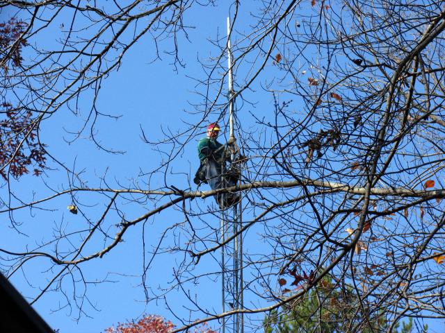
From his vantage point, Louie confirmed that the antenna would (as we suspected) come into contact with branches on four different trees; Don will be calling a tree service on Monday. Until then, the antenna will be fixed in one position (we estimate pointing at about 60°)
Now this is a bit unusual (some might even say "odd")..
Don and Karen had obtained a plastic owl:
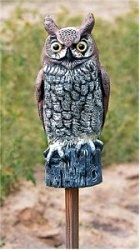
The idea was to place the owl atop the mast to discourage birds from landing on the antenna. Unfortunately, Louie forgot about this, so the mast had to come down to receive the owl which Mike had given a (.. how to put this ..) "rectal enlargement" to receive the 2" OD mast.
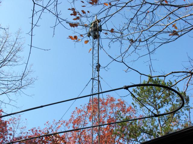
The owl going up; that's one of the "trombone" elements on the roof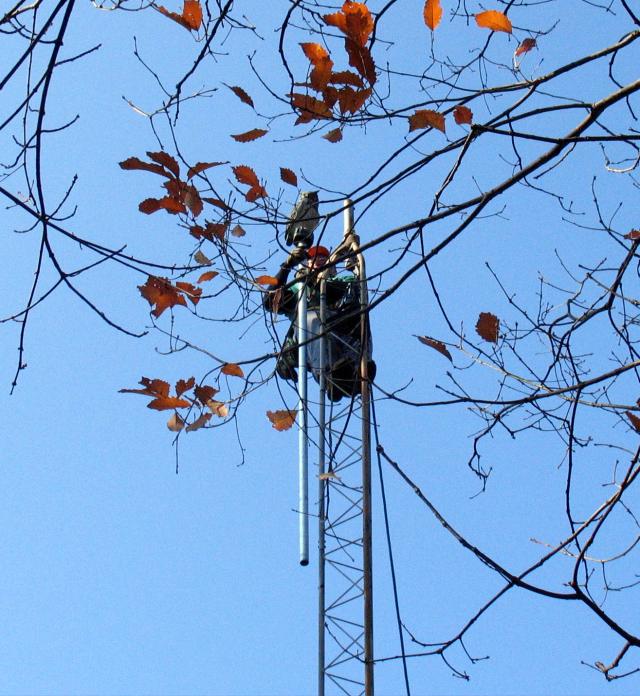
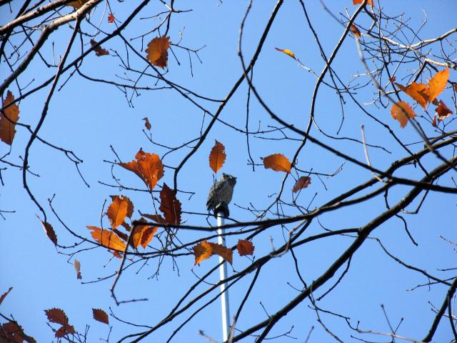
The owl's name? Hoot Gibson..
After the team left yesterday, Don spraypainted the EHUs flat black. This has to be the "stealthiest" boom in the world!
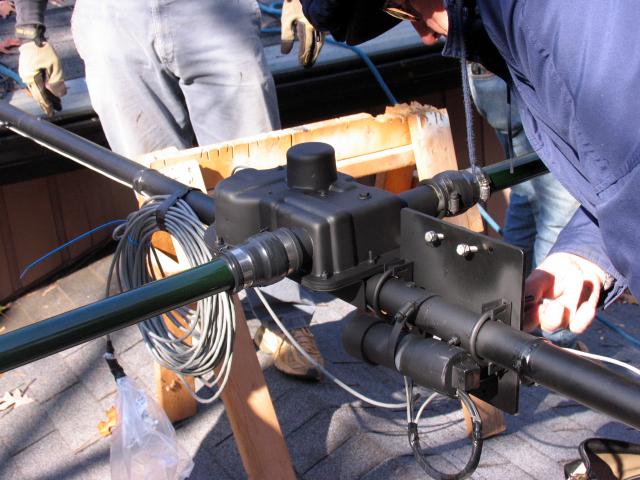
Once the owl and mast were installed and locked down, it was time to rig the ropes to haul the SteppIR up the tower. The assembled antenna weighs only about 50lbs so it was one-man on the rope, one man on the tower. It took some wiggling (and Don N4HH on a "pusher pole") to get the elements past the trees:
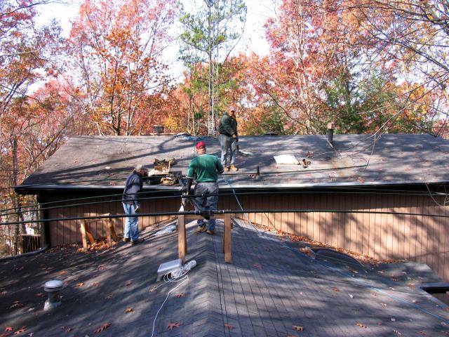
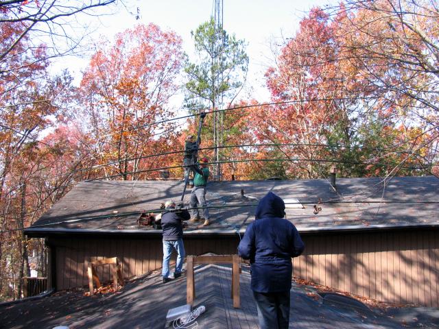


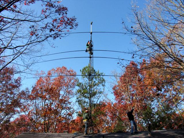
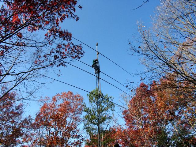
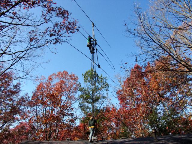
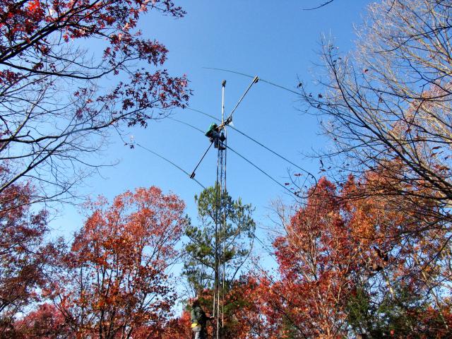
The mast mounting plate is on the boom between the two ESTs which form the "trombone" Driven Element -- so we couldn't use the conventional technique to position the antenna on the mast.
The real trick was to orient the elements so they were vertical and then slip the Driven Element over the mast/owl:
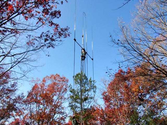
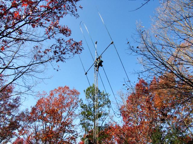
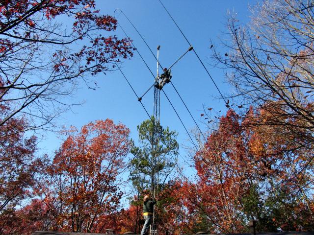
Once that was accomplished, Louie was able to bring the antenna back to horizontal to attach it to the mast. And that's when we found a problem:
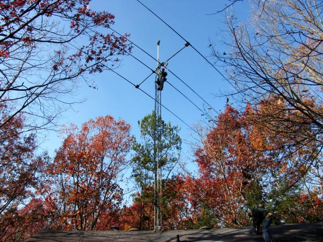
We'd apparently mounted the boom-to-mast plate rotated 90°! That is, we'd used the holes/Ubolts (meant for the mast) for the boom connection. Y'see we didn't have the mast yesterday to try out on the bracket to make sure we had it right. We had a 50-50 chance of choosing the right orientation -- and we guessed wrong. The effect of the error was that the Ubolts were now too short to attach the mast to the mounting plate.
A word for the next installation: the proper orientation of the plate has two unused holes in the plate facing down, parallel to the boom, NOT like this:
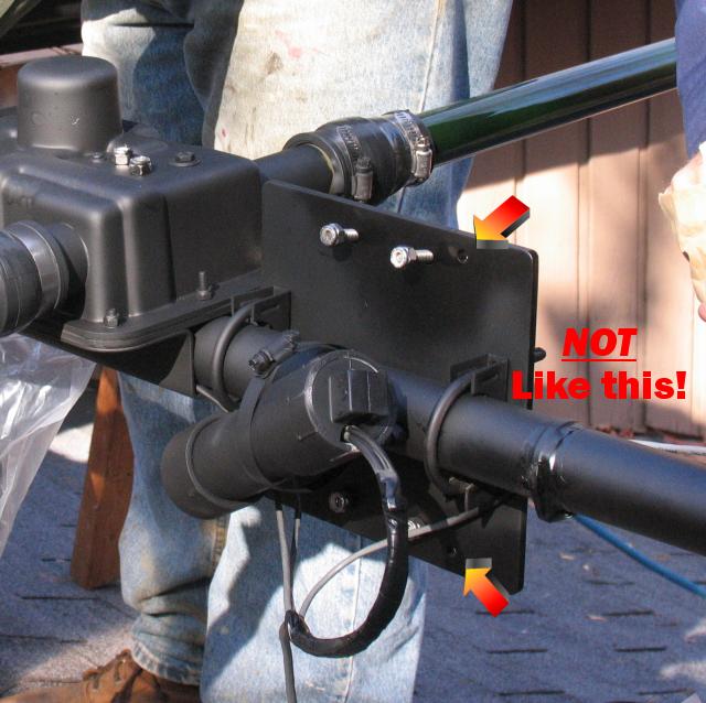
This is the WRONG way;
..and I'm not about to climb the tower to photograph the right way!
This wouldn't have been so bad if we had discovered it on the ground or even on the roof. But Louie found the mistake while strapped to the tower 30' in the air. He had to remove the plate, rotate it and put it back -- in a 15-20 knot breeze at about 40° F. But he did it:
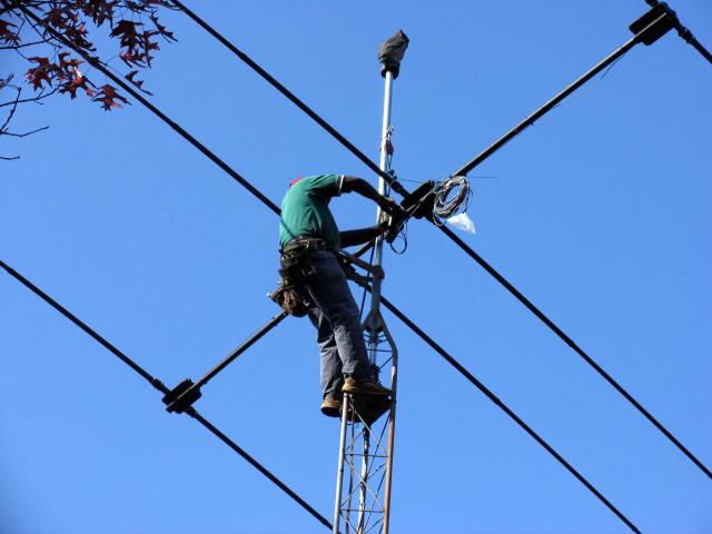
After getting the plate turned around, secured and the boom mounted to the mast, Louie oriented the beam to a heading of 60° which is the heading Don had preset into the Yaesu 800D rotor. This heading is presently the best we can do until some of the trees are trimmed. No rotor operations today!
All that's left is to:
- Attach the coax
- Re-attach the end of the old dipole used for 80M
- Climb down
- Tape off the coax, SteppIR control cable and rotor cable and drop them to the hamshack window
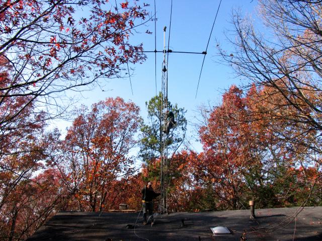
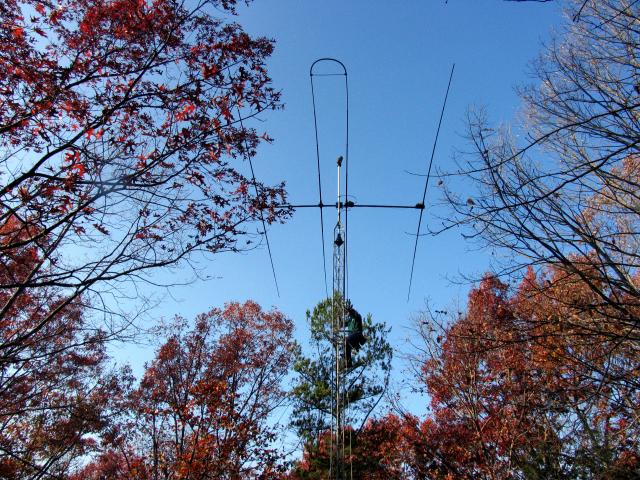
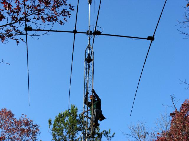
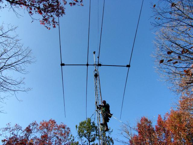

We hooked everything up and checked the SWR. Found it satisfactory on 20-10M but out of spec on 30M and 40M:
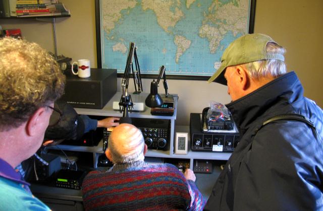
We suspect that since the Driven Element is in light contact with TWO trees, that may have some effect! Once the trees are trimmed, we're confident that we can tune all bands to 1:1 SWR.
We all left for home (Don actually left first; he had a meeting commitment) so the rest of the story will have to wait a few days!
The sun was setting as we headed for home so I took one last photo of the antenna in place. Even late in the year with the trees getting bare, this is one stealthy installation! And, notice, no birds on the antenna..
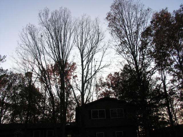
Monday, November 20
Don reports that the antenna works fine on 17M:
|
My first QSO was with 9A2YM, S9+20 on 17. The second was with 5A7A, "S9, big signal" also on 17. |
November 22
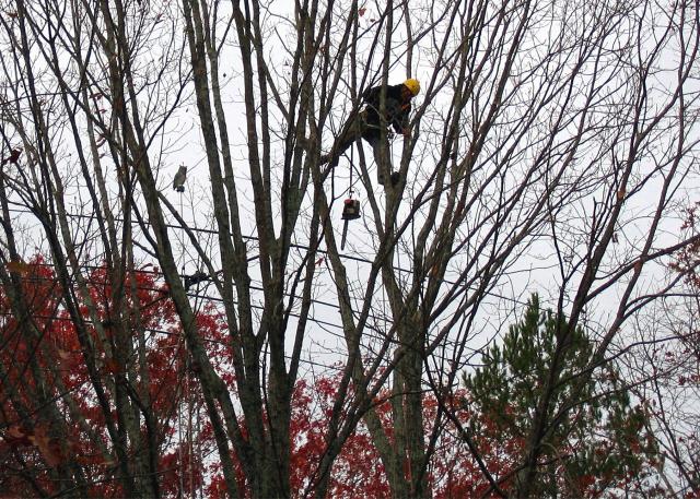
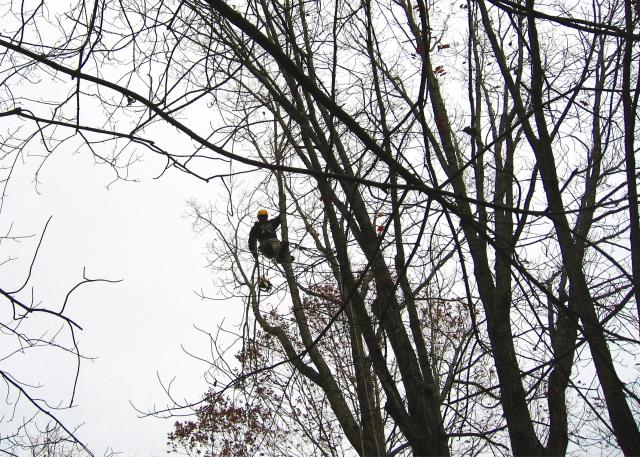
The tree crew came this morning at 7:30a and proceeded to remove branches and, in one case, a whole pine tree:
November 23
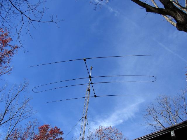
..and here's how it looks today, fully-rotatable, 200' HAAT:
From Earth to E-Layer..
..
You can see the story of my SteppIR 3El installation by clicking HERE.
Site designed and hosted by


